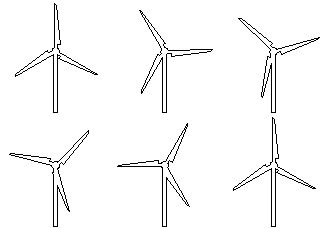
To be or not to be
Sein oder nicht sein
Believe or not believin'
This is the question here just so
Someone swears on 6-zylinder cars, condescending on all 4-zylinder drivers.
In the field of
"wind energy plant design" it is similar. You can build in a lot of
experience in the rotor or the subsystems, but hosts of 'experts' want to
make their own faults. Hosts of experts don't believe in the Bernouilli law,
in the theorem of momentum, the law of the conservation of energy by Mayer or
the continuity equation. They hope to invent the absolute overwhelming new
machine, but if you have a look into old windbooks you will see easily:
everything was just yet on the stage. There exists till now no concept that works more
economic than the "free running turbine with a horizontal axis" as physicians spell.
But: "The market takes the decision."
It is for example absolutely unimportant if the rotor of such a windturbine has
2 or 3 rotorblades. The energy output at a windsite counts, the investment costs,
the lifetime with corrosion problems, and, and . . . .
The market wants a windmachine with
- simplest handling of the windturbine without special training of the user
- long operational life (20 to 30 years) with few maintenance intervals
- resistence of the components against all climatological conditions such as heat,
cold, dryness, atmospheric humidity, salt air, rain, snow, icing up, rime, lightning
and quicksand
- output at low wind speed, i.e. starting at low windspeed, the output is
hereby always minute
- simplest construction design with easily exchangeable components (module groups)
- divisibility of the machine with regard to size and weight for the purpose
of transporting the module groups or subsystems (think of the high sea container)
- low capital and operating costs. (a dream?)
The engineer has to solve these demands and therefore he needs a simple but high developed, say
"sophisticated solution".
Let's make a naive, basic example:
A motor car with a mileage performance of 200 000 km has had an operational life of
approximately 4000 to 5000 hours. During this time the car was frequently in the workshop
and the driver was permanently present to help with breakdowns. A WEC must be in full
action approximately 6000 to 7000 hours in a single year and should run, more or less,
unattended.
In both systems you have srews, bolts, nuts, cogwheels, bearings, sealings,
hydraulic elements, electric parts, housings . . . . .forces, moments, oscillations and
vibrations, corrosion . . . . and a lifetime factor of 40 !
This factor is the genuine, the true problem in windenergy utilizing systems.
Here my conviction.
Philosophy of the wind power plant
designer "a posteriori"
If you want to use the nonpolluting regenerable windenergy, there exists not the
only or the solely solution. Previously the designer has to decide what kind of
energy is desirabel. Is it only mechanical energy you are interested in,
i.e would you only let turn a shaft with a crank drive to run the stroke rod
of a water pump in a well? Or do you want electricity a kind of high-grade
energy? The answer in the first case is the multiblade western mill, the most
economic system for water pumping, if, the water table is not very deep,
i.e. not deeper then 30 to 35 meters. Is the sub-soil weater level deeper
you need an electric driven plunger piston or rotary pump and you need electricity.
And for the generation of electricity the outstriping system is the "high speed
free running turbine with horizontal axis".
All is not gold that glitters, as the saying is. Not every windsystem which turns
is an effectiv economic windenergy conversion system.
Types of windturbines:
Three important criterions arrange an usefull typology:
We can divide all plants according to
1. Position of axis: horizontal or vertical
2. Resulting force acting by the flow: lift or drag
3. Tip speed ratio: high speed running machines or low speed running machines.
The tip speed ratio is a dimensionless value, the ratio of the highest occuring
circumferencial velocity at the rotor, i.e. at the rotor tip, to a certain windspeed,
for example the wind speed concerning to the rated output.
The clickable pictures show the typology.
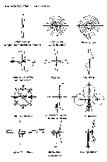
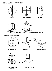
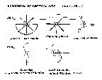
This paper deals only with the "high speed free running turbine,
with horizontal axis, only a small number of rotorblades and with
high lift forces and low drag forces acting at the blades".
Remarks for the layout of wind energy converters
in short notes:
Number of rotorblades:
The designer decides this point. The blade-element-momentum-theory says: each further rotorblade brings
a little bit more power, but this is not running linear, i.e. a two blade rotor
brings not double power than an one blade system.
Very important also is the planned tip speed ratio for the decision: how much
rotorblades will have the rotor. High tip speed ratios mean more and more influence
of the friction effect at the airfoil section. An evident jump can do the
powercoefficient, if the quality of the airfoil, the lift to drag ratio LDR increases.
The number of rotorblades z is insignificant (see the following diagram).
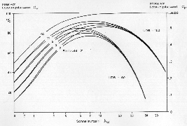
If you design low tip speed ratios, i.e.low running machines like the multiblade
western mill for water pumping, each rotorblade more brings a certain amount more for
the powercoefficient value. Further the starting torque is better with more
rotorblades build into the rotor, an advantage for the water pumping system also.
High speed running machines for generating electricity, with only 2 or 3 rotorblades
have starting problems, but because you need an effective storm protection anyhow,
the rotor control must be pitch control, either stall regulation or in opposite
direction, zero lift. Supplementary, if you have pitch control, the starting behaviour of such
a high speed converter is much more better than without this control system.
Nature is symmetrically,
forget the one-blade-rotor. You can't save one blade complete
(i.e the costs), you need at least
a compensating arm (mass) for the one blade.
Further with each rotorblade more,
there is not only an increase in power, the loading of all components by the aerodynamic
and other forces will get more and more harmonic. Everybody likes to drive
a 12-cylinder car more than only a 4-zylinder vehicle.
For big plants, the rotor costs roughly 40 % of the system. Therefore the question:
2 or 3 rotorblades makes sense.
Recommendation:
Plants up to 100 m diameter should have 3 rotorblades.
Plants with more than 100 m diameter should have only 2 rotorblades.
Naturally the named limits are blurred.
Rotorposition:
The lee-position of the rotor, the downwind-position, is an inherently
stable position. The position of the rotor infront of the tower,
luff or windwards, is a labil position. If in this position a small disturbance
occurs, the rotor will move downwind in the direction of the airflow.
The designer is free in his decision, but he should have a sincere
look to the typ of the tower. A lattice pole or tower is the cheapest
tower at all, but the disturbed region behind such a tower is fatal
for lifetime of the rotorblades rotating behind this tower.
Always in the influenced region behind the tower there will collapse
the lift forces as well as the drag forces and the bending moment
of the baldes will become zero. This is an immense alternating stress.
A little bit more expensive is the tubular tower guyed with rods or ropes.
The tower wake there is not so intensive as in the case of the lattice pole
and therefore both rotorpositions are possible. Today modern plant have generally
cantilever selfsupporting steel-tubes towers up to 100 m height, for example
for a 1.5 MW wind energy converter (ENERCON E-66, Nordtank 1,5 MW).
The rotorposition is windwards.
Recommendation:
A horizontal axis wind energy converter has a selfsupporting cantilever steel-tube
tower and the rotor rotates in windwards or luff position.
Tip speed ratio (lambda):
The blade-element-momentum theory says: as higher as you choose the tip speed ratio,
as higher will become the powercoefficient and as slender and thinner will
turn out the single rotorblade. For high tip speed ratios you need only a small
cordline depth of the aerodynamic airfoil section to receive the needed liftforce
for the highest possible powercoefficient. This leads to a severe problem and you
have to agree to a compromise. With extreme high tip speed ratios there exists no
kind of material to build up the rotorblade. The cross-section will become so tiny
that the blade can't withstand all acting forces. A special phenomena, lateral buckling,
takes place. Not even carnbon fiber composite material leeds to a satisfying solution.
If you optimise rotorblades in such a manner, they look like ropes and act scared flexible.
This is a huge lifetime problem also.
Modern wind energy converts run today with tip speed ratios lambda between 6 and 12.
The designer determins the design starting point himself. He determins the rotational
speed of the rotor, the rated speed for the rated power. But he has to look to the
rotor diameter because he should not reach a tip speed near the sound velocity, and
he has to look to the energy-transmission-chain: rotor/gearbox/generator as well, naturally
if there is a gearbox at all.
The tip speed should not be choosen higher than 100 m/s. The rotational speed of the generator
can be 1 500 rpm (50 Hz frequenzy) or 1 800 rpm (60 Hz frequenzy) if you want electricity
with constant frequenzy. With this data you can calculate the rpm of the rotor at the design point.
A second value determins the tip speed ratio lambda, it is the wind speed of the
layout point at which you get the rated power. This value is also choosen free by the
designer. You can take for it the annual average windspeed of the site, or the frequent value, or
a very low or a very high windspeed.
The choosen windspeed, i.e.the lambda value, depends also on the tower height,
because windspeed increases parabolic with the height. Helpfull to judge the
formation of the windspeed is the surface roughness which varies with the
terrain shape, the topography or the inbuild natural or artificial obstacles.
The annual frequency distribution of the wind depends on these effects also.
For the mathematical description of the frequency distribution of the windspeed
you can use the Weibull-equation. In this equation you need some constants for
describing the terrain shape, but this mathematic approach can be very
unrealistic in regard to the only calculated energy output in kWh per year.
The annual energy output depends also on the value of the installed power,
i.e on the size of the generator refered to the rotorarea in squaremeters.
Recommendation:
For a highspeed free running turbine with horizontal axis choose a tip
speed ratio between
6 and 8 for the design point (rated power),
but do not exceed a tip speed of 100 m/s.
Installed power, power rating (Watt/sq.m):
Windenergy and similar solarenergy is an energy-rare offer by the nature.
For high power you need a huge area solarcollectors or a huge area
influenced by the rotorblades of a wind energy converter. This means you need
large diameters, for example more than 60 meters for megawatt-plants.
Therefore an important figure for the designer is the power rating, the installed
capacity referring to the rotorarea.
First of all you have to think about this: What do you expect from the wind?
What do you want?
This is an energyphilosphical question. Do you prefer a constant power
mostly within the whole year, for example at an isolated site without a grid?
Or would you like to earn the highest possible number of kWh, summarized
the whole year, for example to feed this energy into the grid?
This are two absolutely different aims.
If you want constant power all over the year, the power rating should be low.
A small plant, say 100 sq.m rotorarea or 11,28 m diameter, is then provided with
a 3-kW, 5-kW, 8- kW or 10 kW-generator, equal to a power rating of 30, 50,
80 or 100 Watt/sq.m. This low power rating delivers a certain power duration
curve (see upper diagram in the following clickable picture).
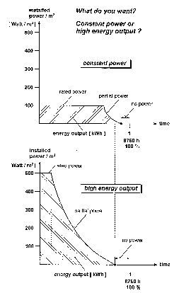
If you put a 50-kW generator on the top of the same machine, you have a power rating of
500 Watt/sq.m. Naturally the structure then must be a little bit more resisting
in all subsystems like rotorblade, bearings, shafts, gearbox-parts a.s.o.
With the higher power rating the power duration curve shows now another shape (see
lower diagram in the clickable picture). In both curves the included
area is the total energy output in kWh harvested out of the wind and accumulated in
one year. Plants with a higher power rating need for starting a higher wind velocity.
Low power rating machines start at lower wind velocity, the losses are smaler,
the share of dead calm times is lower also than if the power rating is very high.
It's now the skill of the designer to find out the optimal power rating for a
certain site, with a given annual frequenzy distribution of the wind speed (Weibull),
considering the tower height for the increase of the windspeed with height and the power
characteristic of the individuell powered machine, with different classifications
according to size of the generators and different powercoefficient values and curves
for the different sizes.
This is a nice optimisation challenge.
Recommendation:
At good windsites and big machines (high towers, up to 1,5 MW each) you can choose
a power rating of up to 500 Watt/sq.m.
At bad windsites, a power rating of
100 Watt/sq.m is enough.
Airfoil sections:
For highspeed running horizontal axis wind turbines you must build rotorblades with
the best aerodynamic airfoil section you can get. You have to look to the highest possible
lift to drag ratios (LDR) at the correct Reynoldsnumber (roughly lower than 500 000).
For NACA airfoil sections you will find measurements only for higher Reynoldnumbers,
say 3, 6 or 9 millions. This can become a problem. If you want to build the rotorblade
in wood or metal sheet, the shape of the airfoil can't have an inwards
buckled lower surface, like all laminar airfoils have. In this case a straight lower
surface is more advantageous. But these airfoils do not reach very high lift to drag ratios.
No problems you get with rotorblades build in fiber reinforced plastic material,
with glas or carbon fibers. Indeed you need first a positiv primary model from which
you can mold for example two negativ halfshells. as third step the normal semimonocoque construction
of rotorblades in series can take place. The costs for this tripartite 'construction
chain' are the same. It is unimportant if you choose an ineffectiv airfoil or an airfoil
with the highest possible lift to drag ratio, the costs are the same.
Recommendation:
A high speed running horizontal wind energy turbine should have rotorblades with
laminar airfoil sections like the FX 63-137 or the NACA 642
-415.
If the claim is not so pretentious, perhaps in fact of the used construction method
(wood, metal sheet), a sufficient airfoil section is the Clark Y or the NACA 4415.
This was my conviction
Try your very best
But, if at all, why always the horizontal axis machine and not the vertical axis
plant? Click here and get some more informations.
 doerner@ifb.uni-stuttgart.de
 Since 7th of mars 1997.


 doerner@ifb.uni-stuttgart.de